Configuring Layer 3 Routing on EtherWAN Switches
In a previous article we discussed the differences between Layer 2 and Layer 3 switches. Layer 3 switches now often support unicast and multicast routing, and even the Virtual Router Redundancy Protocol (VRRP). Depending on the size, configuration, presence of multicast devices, and external connections, different routing methods may be needed. Refer to the table below for the routing methods supported by EtherWAN Layer 3 switches. (Note that VRRP is technically a redundancy protocol and not a routing protocol, but is included here because it is a Layer 3 function).
| Model | Static Routes | VRRP | RIPV1/V2 | OSPF | PIM(Multicast Routing) |
|---|---|---|---|---|---|
| EX78900X | ☑ | ☑ | ☑ | ☑ | |
| EX73900X | ☑ | ☑ | ☑ | ☑ | |
| EG97000 | ☑ | ☑ | ☑ | ☑ | ☑ |
| EX78900E | ☑ | ☑ | ☑ | ☑ | |
| EX78900E | ☑ | ☑ | ☑ | ☑ | |
| EX75900 | ☑ | ☑ | ☑ | ☑ | |
| EX78900 | ☑ | ☑ | ☑ | ☑ | |
| EX73900E | ☑ | ☑ | ☑ | ☑ | |
| EX77964 | ☑ | ☑ | ☑ | ☑ | |
| EX77900 | ☑ | ☑ | ☑ | ☑ | |
| EX73900 | ☑ | ☑ | ☑ | ☑ | |
| EX83304 | ☑ | ☑ | ☑ | ☑ | |
| EG99000 | ☑ | ☑ | ☑ | ☑ | ☑ |
Let’s go over how to configure the various routing protocols on an EtherWAN switch.
Jump to:
Static Routing
RIPv2
OSPF
Static Routing
Static routing is the manual creation of a fixed path in the switch or router to another network. This requires creating a Router Port and then entering the path to the connecting network. Static routing is especially useful for routes that seldom change, and in situations where there are only a few routes to other networks. There are several advantages to static routes. They are easy to configure, they require minimal CPU resources, and the give an administrator full control over the network routing.
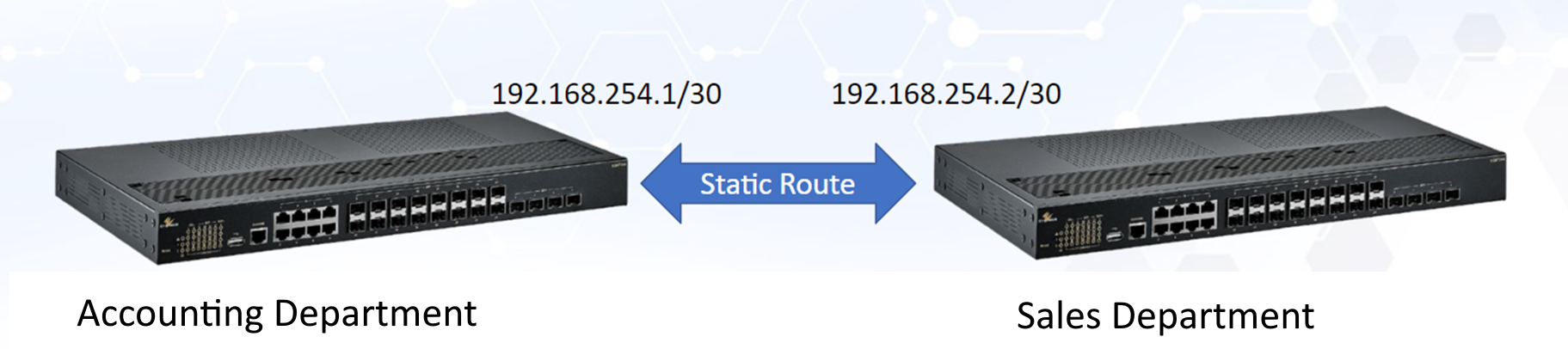
In the above example, the Accounting and Sales departments are on separate networks. A static route is used to connect them, using a CIDR of /30. This connection will be exclusive to the two switches, and will not include random traffic from other devices.
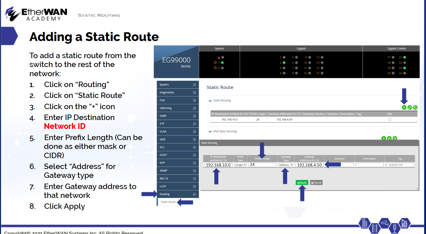
Adding a static route using the GUI management interface on EtherWAN switches is quite straightforward. We will use the EG99000 for our example:
In the menu on the left, navigate to Routing → Static Route, then click the “+” icon at the top right. Enter the IP destination network ID, and select prefix Mask or Length in the second field, and the corresponding entry in the third. Select Address for Gateway Type, then enter the gateway address to the connecting network. Then click Apply. The Description field can be useful for documentation, but it is not required. NOTE: Remember that static routing must be configured on both ends of the connection.
RIPv2
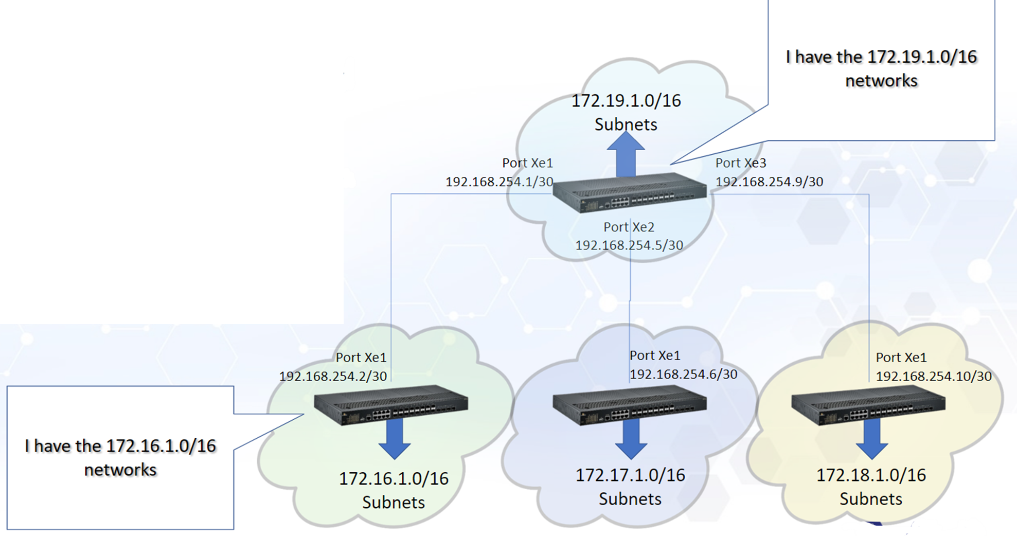
RIPv2 is also relatively easy to configure, but is somewhat limited. It can automatically establish routes between networks, but is limited to a total of 16 "hops." A hop is counted when a packet is passed from one network segment to another. RIP works by having Layer 3/Lite Layer 3 switches or routers send their routing tables to similar devices on the network. Once all of this information has been exchanged and a topology agreed upon by all routing devices, they are said to have "converged."
While RIP has wide industry support and can automatically handle network topology changes, it uses a lot of bandwidth because updates are sent every 30 seconds. Also, RIP does not understand the bandwidth of the connections it maps. To RIP, 2 hops at 1Gbps is faster than one hop at 100Mbps, even though the opposite is true.
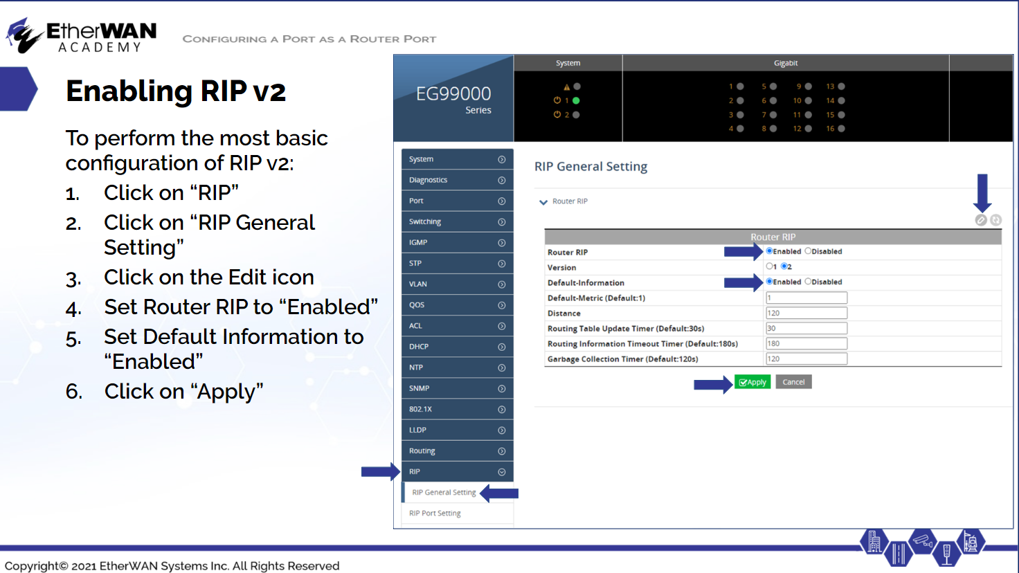
To enable and configure RIPv2, first navigate to Routing → RIP General Setting and click the Edit icon. Set the Router RIP field to Enable, and select version 2. Enable Default Information to distribute default routes. Then click Apply.
Remember that RIP must be enabled on all routing devices that will be distributing routes.
OSPF
OSPF (Open Shortest Path First) is a much more powerful, but also more complicated routing protocol. Its features include load balancing, route summarization, unlimited hop counts, and loop-free topology. OSPF is used for large networks, and is based on routing devices telling their neighbors about their active connections, as well as any neighbor tables received. There is no hop count limitation, and OSPF uses factors like speed, cost, and path congestion to determine the best route. However, these calculations require more memory on the switch or router.
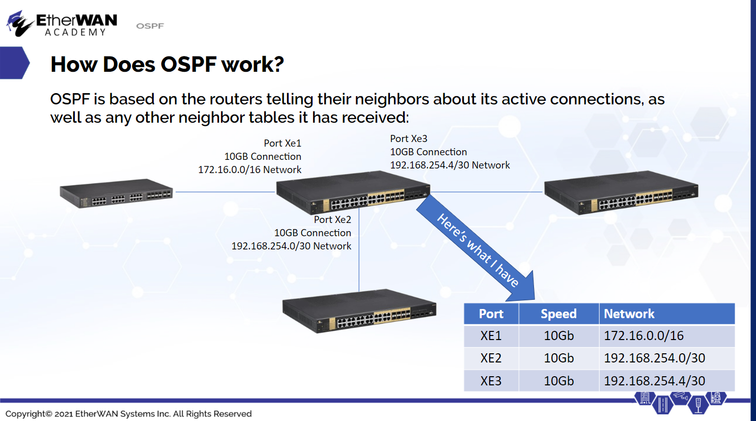
OSPF actually maintains three tables containing network information: the neighbor table for networks directly connected, a topology table created from received neighbor tables, and the routing table, which contains the best routes to each network destination.
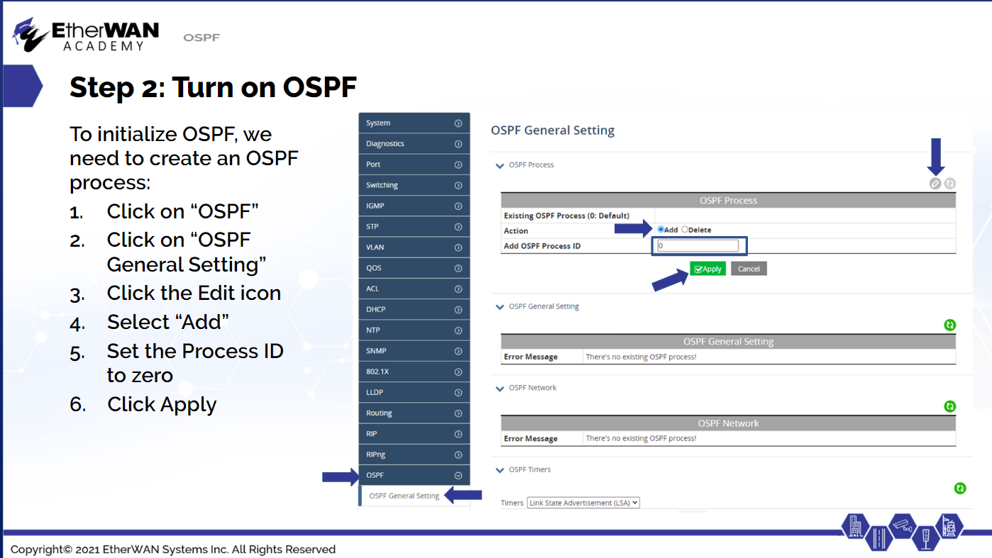
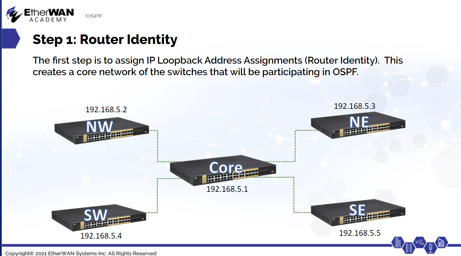
The first step in setting up OSPF is to assign IP Loopback Address Assignments (Router Identity). This creates a core network of the switches that will be performing OSPF routing. Navigate to Routing → OSPF, and click the + icon. Enter the IP address and CIDR for the routing device, and click Apply. Next, turn on OSPF by navigating to OSPF → OSPF General Setting and clicking the Edit icon. Select Add and set the Process ID to zero. Click Apply.
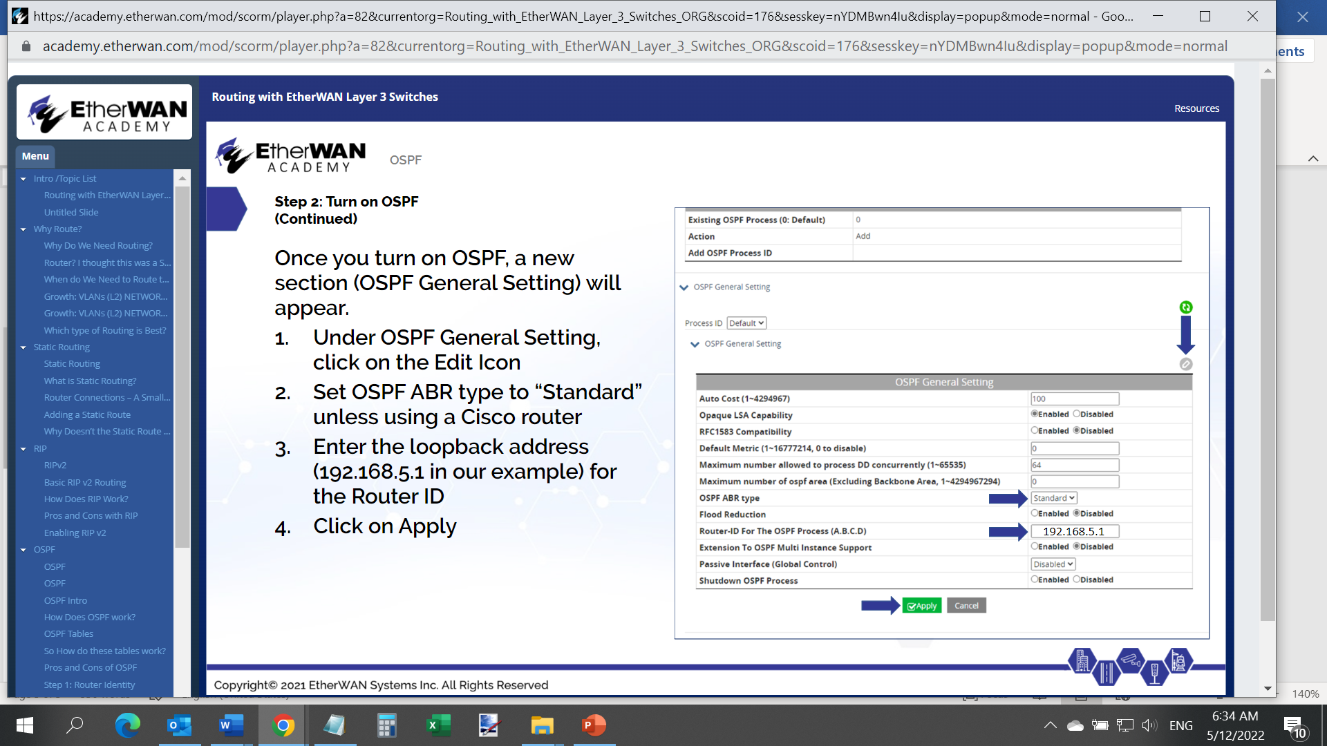
Once OSPF is turned on, a new section will appear. Click the Edit icon for OSPF General Setting, and set OSPF ABR Type to "Standard." Enter the loopback address for the Router ID, then click Apply.
With the basics in place, the VLANs for each switch need to be added so that they are advertised.
The core switch in this example has the following VLANs running:
VLAN 10 - 10.0.10.0/24
VLAN 20 - 10.0.20.0/24
VLAN 30 - 10.0.30.0/24
VLAN 40 - 10.0.40.0/24
VLAN 50 - 10.0.50.0/24
VLAN 60 - 10.0.60.0/24
VLAN 70 - 10.0.70.0/24
Each of these connections can be entered separately, or combined into a single routing entry for OSPF: 10.0.0.0/16 (This would include all 10.0 networks.)
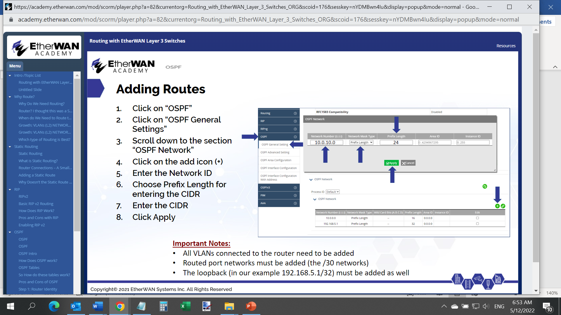
To add routes, click the + icon in the OSPF Network section. Enter the Network ID, select Prefix Length, and enter the CIDR. Click Apply.
That completes the basic OSPF configuration on a core switch. To view all routes known by the switch, navigate to Routing → Route table.


